Tips
As a 3D design enthusiast, it is always rewarding to create, reproduce, or optimise models to improve their efficiency.
Multifunction 3D printers are a prime example of this. The process begins with the manufacturing of various parts to replace defective components, followed by the optimisation of certain parts of the printer to enhance its performance and functionality.
In mechanics, applying force to assemble or disassemble elements is often necessary, but it is not a universal rule. Take the nozzle, for example, which needs to be heated to a high temperature to be tightened or loosened with force, and can sometimes break or be misaligned.
If similar results can be achieved without resorting to force, it represents a significant gain. However, this requires a change in approach and more careful handling, which can prove to be more complex than it seems.
We encourage you to explore this alternative method, which promises effective results in all aspects.
A few tutorial video can be found on swiss3Dc YouTube channel, others in digitalised GIF.
Need a specific tutorial video, feel free to request it.
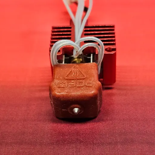
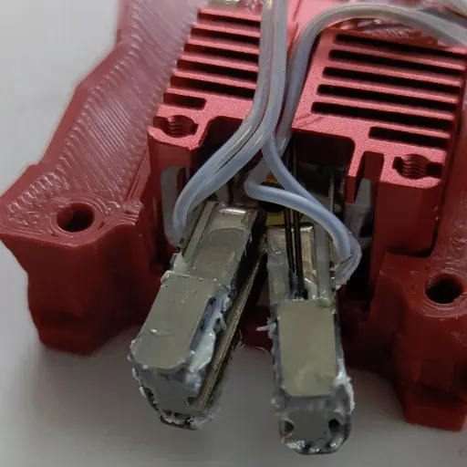
*MCH wires*
We strongly recommend that you avoid bending the MCH
(Metal Ceramic Heater) rigid wires at the base multiple times, as this practice can significantly increase the risk of breakage at the soldering point. The warranty can be void for new installed MCH heaters.
To enhance your experience and ensure the durability of these components, we have intentionally left an extra length of wire. This additional length is designed to provide you with the necessary flexibility when you need to open the DHB for nozzle replacement.
By following this guidance, you can help maintain the integrity of the wires and facilitate a smoother process when performing nozzle swap tasks.
There is a white silicone material surrounding the wires close to the ceramic heater; it might emit a bit of smoke first times and may flake off, but it does not affect the performance of the element.
Since 6 months of intense use in our facility, wires never broke, same for the Voron sample given in customers hands a few hundreds of times visiting our booth during RepRap festivals or shows.
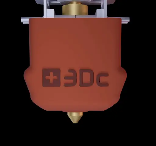
Removing the Silicone Sock
Underneath the silicone sock, you'll find a spring clip that plays a crucial role in keeping the entire assembly secure and stable.
When it's time to remove the clip beneath the silicone to access the nozzle, remember that you don't need to apply excessive force; a gentle touch on one side is all it takes.
Simply press down lightly with your fingertip on the area where the clip is located (and only where the silicone protrudes) to release it effortlessly. You'll notice that one side is often easier to unclip than the other, so start with that side for a smoother experience, then press down on the other protruded side down too.
To reattach it, use just your fingertip to press at the center of the clip and silicone sock. Take a moment to carefully locate the nozzle and push it back up; you might feel a slight pinch on your fingertip, but rest assured, this is a sign that everything is being securely and correctly reassembled. Check that you clearly see the nozzle beneath the silicone sock. Trust me, following these simple steps will ensure your device remains in top-notch condition as well as the silicone sock !
With the HSS+C nozzles, as the copper sleeve has a flat end instead of an angle, bringing the clip back to its position might be trickier at the beginning. This is when the fingertip to replace the nozzle is very important. It's best when the clip is lifted nice and flat against the hot-end to take the correct position.
Mounting the MCH Heater
Installing the MCH heater (Metal Ceramic Heater) and thermistor can be accomplished without any tool.
Ensure that the HB groove aligns with the MCH heater, and keep the wires positioned upwards while lowering the heat block.
The clamping should be moderately tight; if it feels loose, remove the Heat Block, gently pinch both sides of the HB Clamp. Be cautious, as excessive pinching may cause the Clamp to break.
Avoid bending the MCH rigid wires at the base, as they may break at the soldering point. We leave extra length for flexibility when opening the DHB to change the nozzle.
We do not apply thermal paste to our hot-ends, as many thermal pastes can become counterproductive when overheated and dried out.
But, thermal past can be applied in the thermistor hole and between the MCH heaters and the Heat Block only, if you wish. Not in the nozzle groove.
When connecting the wires to the board, make sure not to pull on them; they should be installed with some extra slack to avoid any breakage or poor contact.
If there is an error with the thermistor, check that it isn't being strained at the connection, release it if necessary, and ensure that the bulb is properly fitted into the heat block.
Heat Creep - Clog
Thanks to Starlex DHB specific design, both situations should not happen.
If you do meet one of the situations:
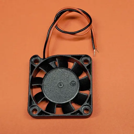
- Verify that the heat sink's cooling fan is spinning freely, especially after installing back the cover, wires might go in the way.
- Make sure there are no wires obstructing the fan's path, which could prevent the blades from turning with no error message.
- Are the wires correctly positioned in the heat sink groove (BambuLab X1C - P1P- P1S) when you attach the fan to the heat sink?
- You can apply thermal paste solely between the brass Heat Sink Connector (HSC) and the Heat Sink (do not use it anywhere else on the hot section!)
- Is the fan connector properly connected and aligned?
- Is the fan mounted in the correct direction ? Air flow should go towards the heat sink.
High flow or not High flow
50mm3/s ?
What truly defines a nozzle as "high flow"? This is a crucial aspect that many people overlook, and it is rarely connected to the actual performance of nozzles.
In fact, the majority of nozzles, with the exception of the CHT type that features a unique internal design, demonstrate comparable melting efficiencies, a fact that is rarely emphasised in online discussions and testing, at least in our experience.
Take the Rapido UHF nozzle, for instance. What is its length? Only a longer melt zone.
The original V6 nozzle from E3D measures 12.5mm, with 7.5mm dedicated to the heat block. The heat break tube adds extra thermal energy to the melt zone, and these nozzles are generally rated between 7.5 to 15mm³/s.
Hot-ends like Slice with the Mosquito achieve their "high flow" status by simply extending their melt zones. This is a key point: it’s not about an inherent capacity for higher flow, but rather the length of the melt zone that makes the difference.
We propose a straightforward relationship with a 0.4mm output: for every mm³/s of flow, you need approximately 1mm of melt zone length.
However, let’s not forget that the properties of the nozzle & filament material also significantly enhance melting efficiency.
For example, we compared a melt zone length similar to that of the BambuLab hot-end, which is 24mm (with 0.4mm output) Calibration tests in Orca Slicer revealed that a standard PLA brand achieved an efficiency of 22-25mm³/s, while using BBL PLA filament pushed that figure to an impressive 27-28mm³/s. Should we label this as high flow? Perhaps not; it’s more about the extended melt zone, thermal efficiency, and the quality of the material used.
Moreover, tests with our patented modified inner path in a V6 nozzle resulted in a remarkable 30% increase in flow rate, revealing or even surpassing the CHT, now that’s what I would confidently define as high flow.
By this simple yet effective logic, a nozzle length of 33mm would equate to at least 33mm³/s. This is the real essence of flow, and understanding this can significantly enhance your 3D printing experience.
50mm3/s
With this same DHB33mm nozzle length on a BambuLab P1S, with quality filament like Nobufil PLAx, we jumped to an easy 50mm3/s with a 0.4mm nozzle, a great performance and an amazing quality layers. This shows that high flow rate depends on many factors, not only one.
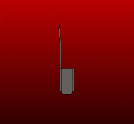
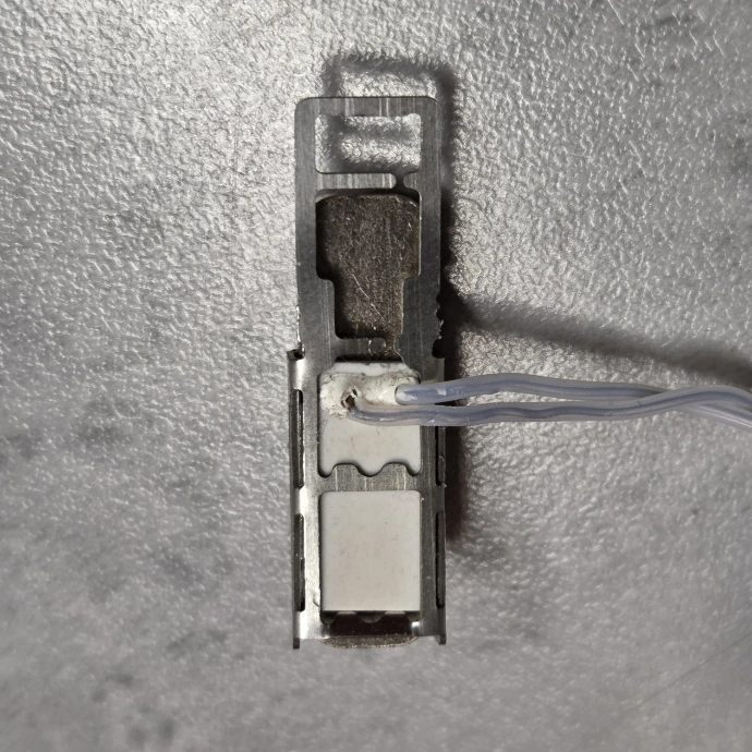
Thermistor mount
Same as the previous "Mounting the MCH Heater" tip, in video.
When connecting the wires to the board, make sure not to pull on them; they should be installed with some extra slack to avoid any breakage or poor contact.
If there is an error with the thermistor, check that it isn't being strained at the connection, release it if necessary, and ensure that the bulb is properly fitted into the heat block.
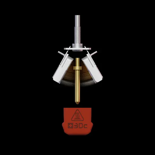
Spring Effect
The Stainless Steel component that secures the Heat Block is called the HB Clamp.
This seemingly simple part is vital to the entire Starlex DHB mechanism. Its thin profile is designed to minimise thermal heat transfer, while the curved design at the top ensures a tight fit for the upper section of the Heat Block.
When locking the Starlex DHB, always check for this "spring effect" before securing it, as it ensures that both Heat Blocks are fully, from top to bottom, in contact with the Nozzle for maximal thermal efficiency.
The upper section can be carefully bent by hand to improve the spring effect.
Heat block groove for the nozzle should always stay clean.
Nozzles Cleaning Cold Pull
When clearing filament from a nozzle, it's crucial to avoid overheating the nozzle, as this can weaken the tempering and sealing functions of the components.
Most plastics soften at temperatures between 45 and 100°C, which is ideal for performing a "cold" pull to remove any leftover filament. The lowest temperature cold pull gives the best results.
Since the fit between the nozzle and the heater groove is tight, any bends or marks can negatively impact thermal efficiency.
Never put a drill bit into the protruded nozzles, as this will lead to total damage of the protrusion.
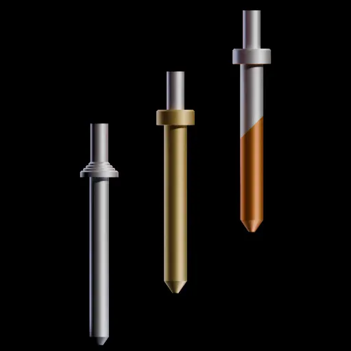
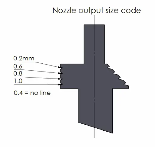
Nozzle output diameter coding
Our objective is to ensure that the coding on the upper ring is as straightforward as possible for optimal visibility.
It is important to note that certain nozzles for the HSS & HSS+C 0.2mm may not feature the top line.
Typically, the 0.4mm nozzle is the one most utilised in the hot-end and does not possess a line.
The HSSC coding is the same as the Brass ring coding, with an extra angled mark on the top edge.
Warping - Material onto the Hot-end
While printing with some materials, warping can occur, leading to the part lifting or becoming detached from one side or corner of the plate, resulting in the hot nozzle dragging across the material and melting the plastic around its tip.
Also blob, when the material does not stick to the plate, due to a nozzle too high from the bed, accumulation of plastic can happen and fill up the hot-end with melted plastic all over.
!!! Always switch off the printer before connectors are removed. Never plug connectors while equipment is on.
If you meet this situation:
- Bring the temperature to around 60°C, not more than 80°C !!! on the printer then switch it off, or carefully use a heat gun, or if the device is unplugged and taken apart, best, immerse it in hot water.
- Remove the silicone cover and metal clip. It might be a little stuck. Clean the excess material on the metal clip.
- Carefully open both heat blocks while they are still warm.
- With your hands, a small clamp, extract most of the soft plastic. Reheat if necessary.
- Take care with the thermistor wires, as they are fragile. No need to remove it.
- Check that no melted plastic remains in the nozzle groove; with a clean nozzle, up side down, slide the nozzle tip up and down in the groove to eliminate any leftover plastic, ensuring the groove is completely clean before using the hot-end again.
- Don’t forget to dry all parts thoroughly before reconnecting and installing them.
!!! Always switch off the printer before connectors are removed. Never plug connectors while equipment is on.
Mounting the Starlex DHB
How to rebuild the Starlex DHB hot-end for a 3D printer upgrade.
It is a very simple step by step process done in less than 2 minutes, without tool for the Starlex DHB system.
Adapted for third party heat sink, in this case, a Grub screw M3x4mm or M3x5mm is needed to fix the brass Heat Sink Connector (HSC)
The easiest way is to start with the nozzle and the HSC, then the base plate (pins facing up) hook both arms onto it, a little spring effect must occur when both arms are mounted.
Before you clamp the arms with the flat spring, rotate the HSC flattened part toward the grub screw. Tight it firmly. Allen 1.5mm or T6 key works fine. T6 (Torx) has a better grip, also recommended to untight it.
Add some thermal past on the HSC on the opposite side of the grub screw.
Make sure the heaters wires are flat against the ceramic in the correct direction, otherwise, they will apply a pressure against the heat sink, limiting the opening of both heat block arms, making it more difficult to remove the nozzle.
Nozzle can be removed better when in working condition, up side down in the 3D printer.
When connecting the wires, do not pull on them, make sure they have enough play to open the arms freely. Forcing the Heaters wires during the open movement will weaken them at the soldering point and break. Make sure they have flexibility and freedom.
The thermistor wire must also be free with no constraints otherwise it might not stay in contact with the heat block and generate a temp failure alarm. Check it sits all way in the dedicated hole. None conductive past can be added in the thermistor hole.
MCH wires position
The heaters wires, from the ceramic MCH heaters are fragile if not mounted correctly. No force should apply to the welding point. Extra length should be left to absorb torsion and bring flexibility.
First, they should be bend once, on the correct side, flat against the heater, perpendicular to it.
The upper wire should have the shortest bend, the longer bend should be underneath the shortest one.
This will avoid wires pushing on the arms in contact of the heat sink when removing the nozzle, therefore give enough opening to both arm. approx 40° open total angle.
Changing Nozzle & G-Code
With this approach of nozzle change, usually filament is stuck inside the nozzle.
On BambuLab 3D printers, there is the cut function, that will make it easy to remove the nozzle. No need to remove the extra filament.
On other printers, you might want to add a G-Code at the end of the process, "End G-Code" in the slicer. Modify or enter the string.
Always check first the specific settings you need, as there can be many variations depending on the process and slicer. This is only G-code examples.
Cura: menu click on Settings->Printer->Manage Printers->Machine Settings, after the first line add from
G1 E-2 F2700 ; Retract a bit (Cura)
to:
G1 E-25 F2700 ; Retract filament at end of print
Prusa:
just above the M84 line
M83 ; set to relative
G1 E-4 F900 ; retract 4mm at 15mm/sec (it can be more than 4mm and faster than 15mm/s ! )
After replacing the nozzle, it's recommended to conduct an auto bed levelling to prevent any damage to the print bed or issues with the initial layer adhesion.
Remember to securely fit the silicone sock with the metal clip and ensure it is clipped all the way up.
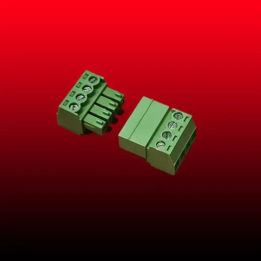
Electrical Connectors
As there is many 3D printers and more connectors, a pragmatic solution we propose is a reliable 4 pins screw connector, 2 for both heaters in parallel, 2 for the thermistor.
It gives flexibility in most case.
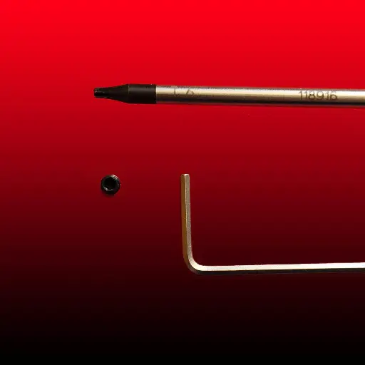
Grab Screws
At Swiss3Dc, our solutions focus on minimising or completely removing screws and grab screws.
When adapting the Starlex DHB hot-end to various existing systems, we leverage the existing tightening methods to install the Hot-end.
A handy tip for Allen hex grab screws is to use a Torx screwdriver to loosen a stubborn hex-tightened grab screw. This approach tends to be effective in many situations.
Always check the tightness of any screws on the delivered products before mounting it on the printer.
Grab screws are usually M3x4mm long, keys are 1.5mm allen or a T6 Torx